
Mesh generation of C-mesh
Target: Generate C-mesh of airfoil RAE2822 by Pointwise.
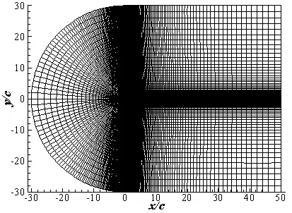
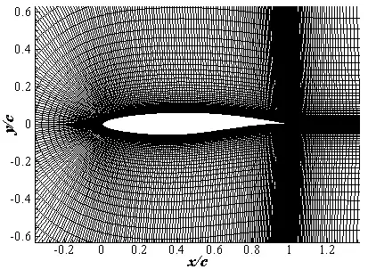
Fig1. C-mesh of airfoil RAE2822(local)
Steps:
1. Import airfoil database.
The geometry you will use for this example is in the file named RAE2822.dat.
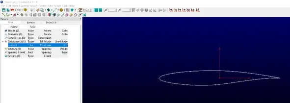
1.1 Start Pointwise.
1.2 File, Import, Database. Select RE2822.dat from the file browser.
1.3 Open
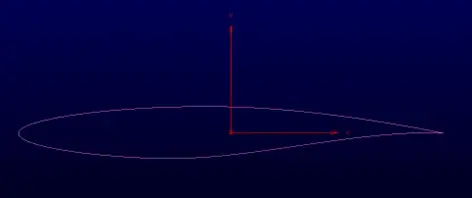
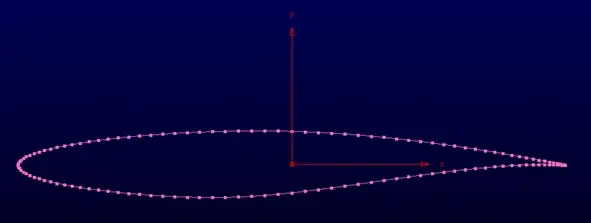
1.4 OK. We can see airfoil as follows.
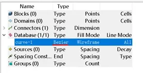
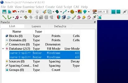
1.5. Select database curves in the List.
1.6 Edit, Spline. We can find the type of curve-1 is changed to “Bezier”. This operation is to ensure the airfoil curve is smooth.
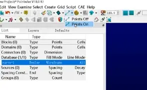
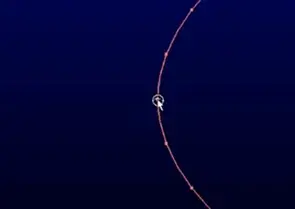
1.7 Select “points on”. Then we can see a series of discrete points as follows.
2. Generate the connectors of airfoil
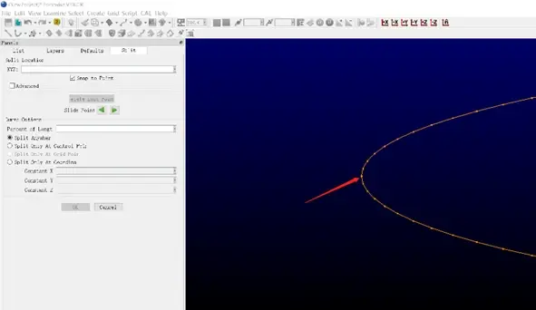
2.1 Select the curve-1, Edit, Split.
2.2 Select the first point of leading edge. Then click OK. We can find the number of Database is 2.
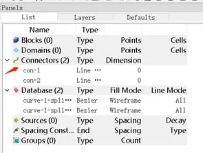
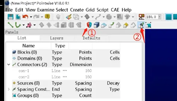
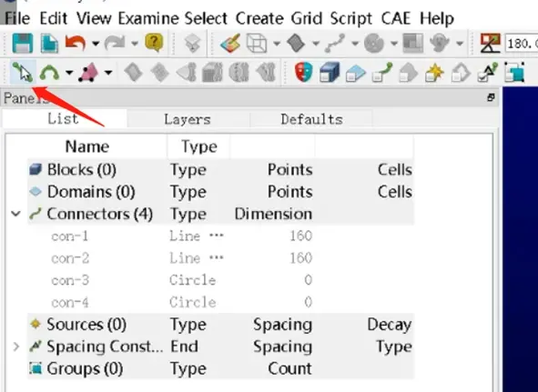
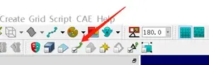
2.3 Click “Connectors on Database Entities” on the Toolbar.
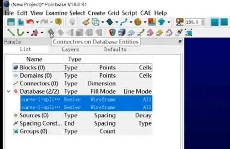
2.4 Two connectors of airfoil appear in the list.
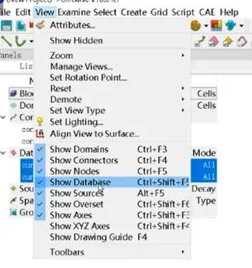
2.5 Select all Databases. View, Show Database. (We don 't need to use Database in subsequent steps.)
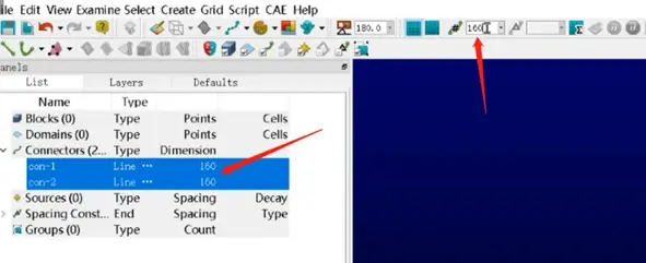
2.6 Select all Connectors. Enter 160 for Dimension. Press Enter on the keyboard. The dimension of connectors in the list is 160.
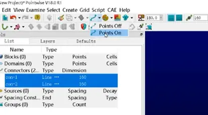
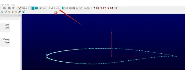
2.7 Points on. The upper and lower of airfoil are discretized into equally spaced nodes.

2.8 Adjust the spacing to ensure the connectors are smooth and consistent with Databases. The operation is: ①All marks off. ② Spacing Constraints. ③ Select the leading edge of airfoil. ④ Enter 0.0005 for spacing and press Enter ⑤ Select the trailing edge of airfoil. ⑥ Enter 0.0002 for spacing, and press Enter.
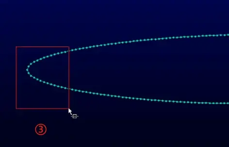

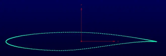
The distribution of nodes is as follows.
3. Create the connectors of farfiled
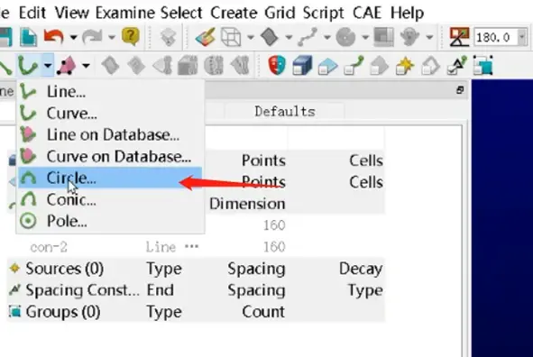
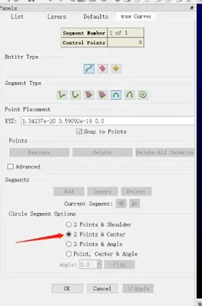
3.1. Draw curves, choose Circle.
3.2 Choose 2 Points & Center
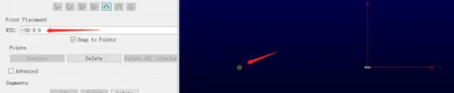
3.3 Enter “-30 0 0” for XYZ, Enter. Scroll the middle mouse, we can see the point(-30 0 0)
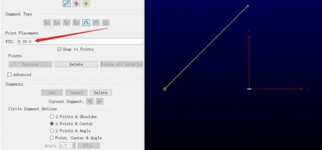
3.4 Enter “0 30 0” for XYZ, Enter.
3.5 Enter “0 0 0” for XYZ, Enter, Apply, OK.
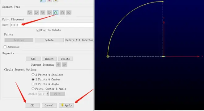
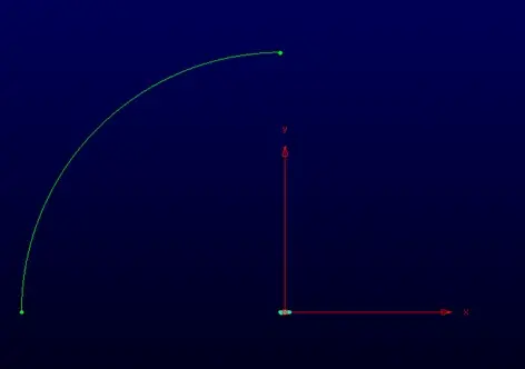
We can see the ? circle as follows.
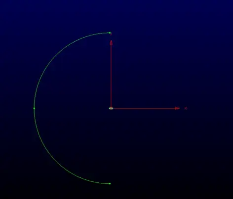
3.6 Similarly, Repeat 3.1 to 3.5. The difference is, the coordinates of three points is (-30, 0 0), (0, -30, 0), (0, 0, 0), respectively. We can obtain another ? circle as follows.
3.7 Point curves.
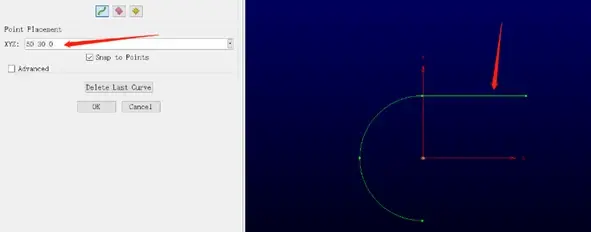
3.8 Enter two coordinates of the end nodes of new curve: Enter 0 30 0 for XYZ and press Enter; Enter 50 30 0 for XYZ and press Enter. We can see the new curve as follows.
3.9 Similarly. We create the other 4 curves. The coordinates are as follows.
50 30 0? and 50 0 0
50 0 0? and 50 -30 0
50 -30 0? and 0 -30 0
1 0 0? and 50 0 0
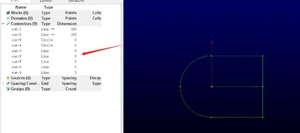
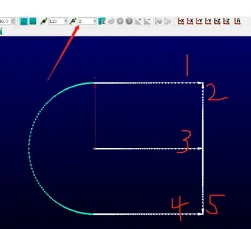
3.10 OK. We can see the new connectors as follows. The number of all connectors is 9.
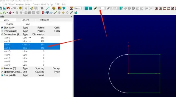
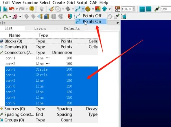
3.11 Select two connectors with circle type. Enter 160 for dimension, which is equal to the dimension of upper and lower of airfoil.
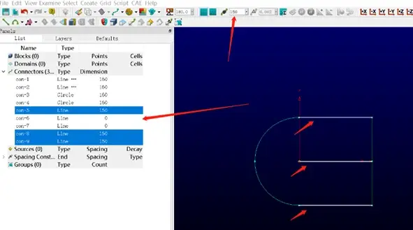
3.12 Select three horizontal connectors as follows. Enter 150 for dimension.
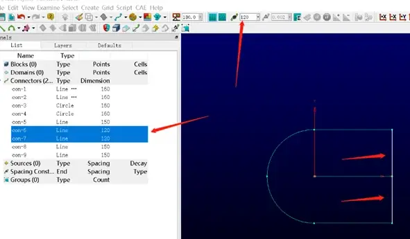
3.13 Select two vertical connectors as follows. Enter 120 for dimension.
3.14 Points on.
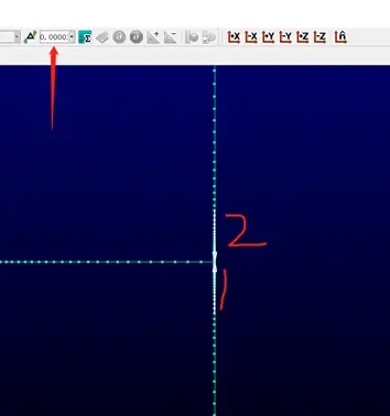
3.15 Set Spacing.
Spacing: 2
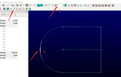
Spacing: 0.002
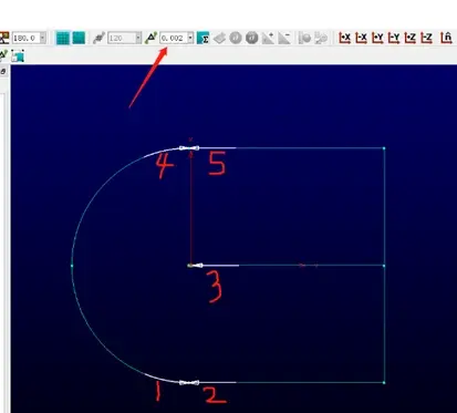
Spacing: 2
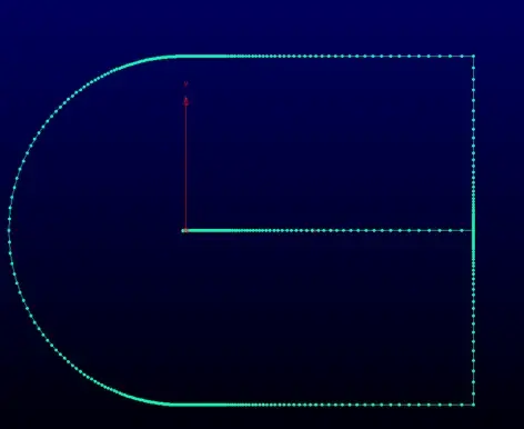
Spacing: 0.00001
The final shape of connectors is as follows.
4. Generate the grids
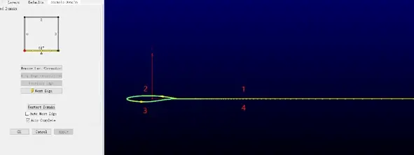
4.1 Structured, Create, Assemble special, Domain.
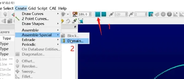
4.2 Select the connectors as follows. The click Next Edge.
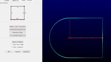
4.3 Select the connector as follows. Next Edge
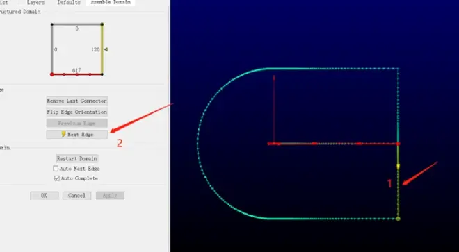
At this time, we can find the domain is produced. Press OK.
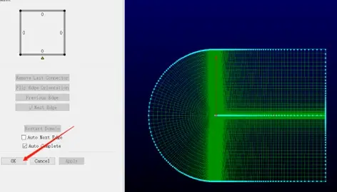
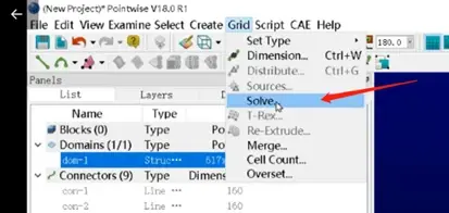
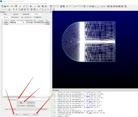
4.4 Select the domain. Grid, solve.
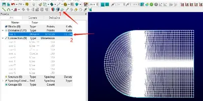
4.5 Enter 3 for Iterations, Run, Apply, OK.
5. Select the solver, set dimension and boundary conditions.
5.1 CAE, select Solver, Choose ANSYS Fluent, OK.
5.2 CAE, Set dimension, 2D.
5.3 CAE, Set Boundary Conditions.
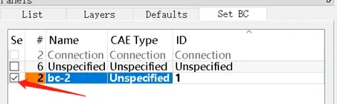
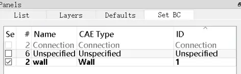
5.4 Select two connectors of airfoil. New
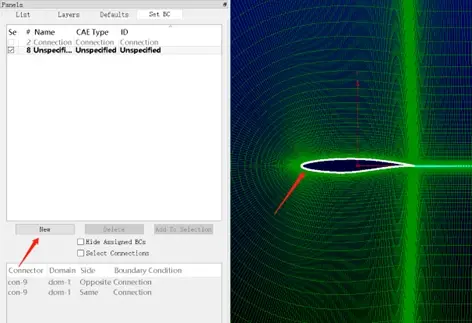
Click the square, and the number is 2. We change the name to wall, and select the CAE type as Wall.
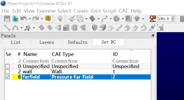
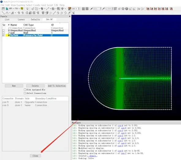
5.5 Select the other six connectors (connectors of farfield), New, Click the square of bc-3. We change the name to farfiled, and select the CAE type as Pressure Far Filed.
5.6 Close
6. Check the Domains.
To ensure the direction of grids is correct, which is one of conditions for the CFD simulation is normal.
6.1 Select the domain, Edit, Orient.
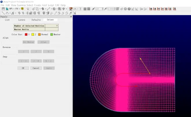
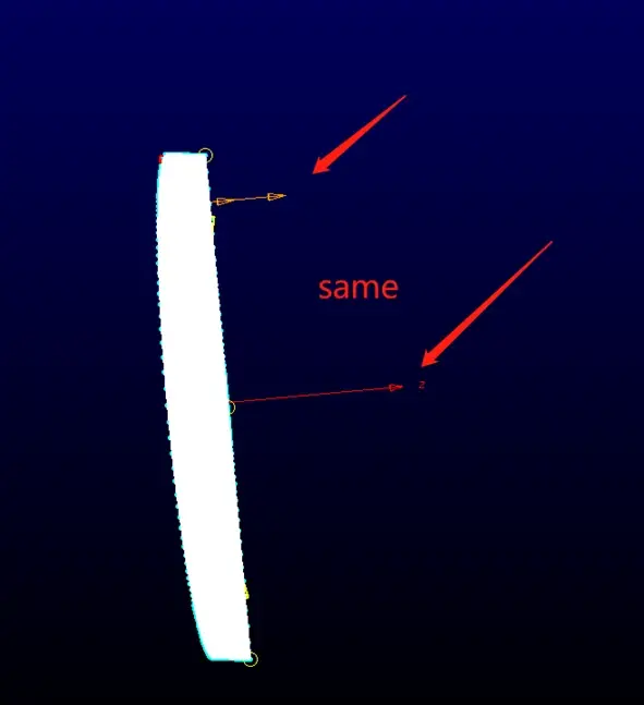
6.2 Rotate the domain (Ctrl + lift mouse), we can see the direction of domain. If the direction is different from that of z, please click J.
The correct direction is as follows.
6.3 OK
7. Save and export the mesh file.
7.1 Select the domain. File, Export, CAE. Select the saved location of the mesh file and input the name. Save.
The saved .cas file is the mesh file, and it will be used for CFD simulation by ANSYS Fluent.
7.2 File, Save. Select the saved location of the pw file and input the name. The pw file is the project file.
All jobs done!
